Model: Split Ultrasonic Open Channel Flowmeter
Protection level: IP65 for display instrument, IP68 for probe
Probe material: The standard configuration is ABS, and anti-corrosion materials should be used in corrosive environments.
product details
Split type ultrasonic open channel flowmeter


Chinese display interface English display interface
1. Button function There are three buttons on the panel, through which the instrument can be debugged. After debugging, the measured value will be displayed on the LCD screen.
![]()
![]()
◇Enter the menu item ◇Move the cursor
◇Confirm menu item ◇Select menu item
◇Confirm parameter modification ◇Parameter modification
2. After the indicator is powered on, press the SET button to enter the first level menu.
3. Input the height value of the probe into the "reference zero point", the position of the "reference zero point" in the menu see "2 range setting" → "1 reference zero point". (The reference zero point of triangular weir and rectangular weir is the distance from the launching surface of the probe to the outlet of the weir trough, not the distance to the bottom of the weir trough. The reference zero point of the Parshall trough is the distance from the launching surface of the probe to the bottom of the trough.)
4. Calibration of "4mA flow value" and "20mA flow value"
4mA flow value: when the instantaneous flow is equal to this value, 4mA will be output.
20mA flow value: when the instantaneous flow is equal to this value, 20mA will be output.
For the positions of "4mA flow value" and "20mA flow value" in the menu, see "V. Setting
"→"3. Menu operation instructions"→"10 Other parameters".
5. When selecting the type of weir and trough, consider the flow rate in the channel, the flow pattern of the water in the channel, and whether it can form a free flow.
The maximum flow rate is less than 40 liters/sec (144 tons/hour), it is recommended to use a right-angled triangular weir; more than 40 liters/sec, it is recommended to use a Parshall trough; the upstream channel is short, and the maximum flow rate is greater than 40 liters/sec. It is recommended to use a rectangular weir. The reference zero point must be calibrated when using the meter to measure. The reference zero point is the distance from the probe to the zero point of the weir trough water level. (This instrument selects Parshall slot by default)
① Triangular weir
To use triangular weir, you can select "on" in the menu "9 weir trough type" → "1 triangular weir" → "1 working status", and select the actual angle of "2 triangular weir angle" to automatically calculate the corresponding water level according to the water level. flow.
② Rectangular weir
To use a rectangular weir, you can select "On" in the menu "9 Weir Type" → "2 Rectangular Weir" → "1 Working Status", and select "0.25m, 0.50m, 0.75m, 0.75m, 0.25m, 0.50m, 0.75m, 0.75m, 0.75m, 0.25m, 0.50m, 0.75m, 0.25m, 0.50m, 0.75m 1.00m, non-standard channel", the meter can automatically calculate the flow corresponding to the water level according to the water level.
③ Trapezoidal weir
To use trapezoidal weir, you can select “on” in the menu “9 weir trough type” → “3 trapezoidal weir” → “1 working status”, and enter the actual weir sill width of the actual channel in “2 weir sill width B”, The meter can automatically calculate the flow rate corresponding to the water level according to the water level.
④ Parshall groove
To use Parshall trough, you can select "on" in the menu "9 weir trough type" → "4 parshall trough" → "1 working status", and the flow formula of parshall trough: Q=Chan. According to the throat width "b", find out the repair coefficient c and index n from the "Attached Table 2 Parshall Trough Water Level-Flow Formula", and enter them into the menu "9 Weir Trough Type" → "4 Parshall Trough" →"2 Repair Coefficient c" and "3 Index n". The meter can automatically calculate the flow rate corresponding to the water level according to the water level.
6. Main technical indicators
Function | All-in-one | Split type | |
Probe selection instructions | Sensor selection instructions: It is recommended to use 100KHz M48×2 probes for No.1-5 Parshall grooves with a measuring range of 1 meter. It is not easy to hit the walls or corners of the Parshall grooves to form false signals. The blind area of the M48×2 probe is small, only 10 cm, and the mounting bracket can be made lower. It is recommended to use 64Khz M48×2 probe for No. 6-25 Parshall slot, with a measuring range of 2 meters and a blind area of 30 cm. | ||
Measuring range | 0.1L/sec~99999.99m | ||
Cumulative flow | Maximum: 4290000000.00 cubic meters | ||
Maximum range of liquid level | There are three types of 1 meter, 2 meters, and 3 meters, larger range and need to be customized. | ||
Level measurement accuracy | 0.5% | ||
Resolution | 3mm or 0.1% (whichever is greater) | ||
show | Chinese LCD | ||
Flow measurement accuracy | Standard weir troughs are 1~5% (weir troughs and channels that meet the requirements of the national standard) Non-standard weirs and troughs are 10-50%. | ||
Analog output | 4-wire 4~20mA/600Ω load | ||
Relay output | (Optional item) 2 groups of AC 220V/8A or DC 24V/5A, | ||
powered by | 220V AC+15% 50Hz, or 24VDC 120mA; | ||
powered by | (Optional item) 12VDC, battery powered, solar powered | ||
Working temperature | Display instrument -20~+60℃, probe -20~+80℃ | ||
Work environment pressure | Standard atmospheric pressure | ||
Working environment humidity | ≤90%RH, non-condensing | ||
Process temperature | -20~80℃; | ||
Process pressure | Standard atmospheric pressure | ||
Communication | Optional 485, 232 communication, MODBUS protocol | ||
Protection level | Display instrument IP65, probe IP68 | Display instrument IP64, probe IP68 | |
Probe cable | without | The standard configuration is 10 meters, the maximum is 100 meters | |
Probe material | The standard configuration is ABS, and anti-corrosion materials should be used in corrosive environments. | ||
Split Product power consumption | The split type uses 24V power supply. The power consumption is 100mA without relay, 120mA with one relay, 145mA for 2 relays, 170mA for 3 relays, and 190mA for 4 relays. The specific power is as follows: Without relay, 24×100mA=2.4W; 1 relay is 24×120mA=2.9W; 2 relays is 24×145mA=3.5W; 3 relays are 24×170mA=4.1W; 2 relays are 24×190mA=4.6W; |
Integrated Product power consumption | The integrated four-wire system is powered by a 24V power supply, without a relay, the power consumption is 80mA, with a relay is 105mA, and a two-way relay is 130mA. 2 relays are 24×145mA=3.1W |
7. Installation
The instrument display part of the split ultrasonic open channel flowmeter should be installed indoors. The room must be well ventilated and free of corrosive gases. The instrument is wall-mounted. If the indoor conditions are not good or must be hung outdoors, it should be installed in the instrument protection box to avoid sun and rain.
Install the probe
The probe of the ultrasonic open channel flowmeter can be installed directly above the water level observation point of the weir trough. The emitting surface of the probe should be aligned with the water surface and perpendicular to the water surface. You can put a spirit level on the upper cover of the probe, and adjust the level of the upper cover to make the probe aim at the water surface. The water level observation point of the Parshall Trough is at a position of 0.1 to 0.5 meters from the upstream of the trough; the triangular weir and rectangular weir are on the upstream side, and the distance from the weir plate is 3 to 4 times the maximum water depth of the weir.
◆Static well installation
In many sites, because there will be garbage, foam or other floating objects on the water surface in the channel, the measurement error is caused or the signal cannot be measured; or because there is no straight channel of sufficient length upstream, the water surface fluctuates severely, so you can use the static well method to solve the problem. Install to solve.
The diameter of the inner wall of the still water well should be more than 50 cm, and the inner wall should be flat without any protrusions and burrs. After the probe is installed, the distance between the probe's launch surface and the highest water surface is> 0.3 meters.

Figure 1. Installation of still water well
Applications:
Mainly used in sewage plants, water plants, mines, water conservancy, power plants, chemical plants, steel plants, smart water projects, various monitoring projects of geological disasters, municipal projects, sponge city projects, urban inland river governance projects, hydrology, water conservancy informatization construction Projects and other industries, scientific and reasonable management system and sound quality control system, realize product traceability management, help product safe and efficient operation, won the China National Chemical Corporation, Harbin Institute of Technology, Baosteel Group, China State Construction Group, COFCO, The trust of representative users in the industry, such as Hengan Group, has accumulated rich experience in on-site disposal of instrument products in various fields.
Field case:

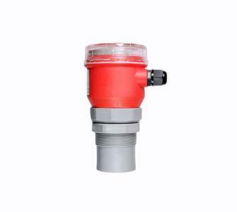
Integrated ultrasonic level meter
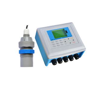
Split ultrasonic open channel flowmeter
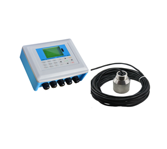
Ultrasonic sludge interface instrument

TOP